Category: Technology
Preparing a Second-Hand Tank for O₂ Storage
We outline the essential steps for preparing a second-hand steel tank for safe oxygen storage, from proper degreasing and rust treatment to thorough drying and inspection. By carefully removing contaminants and moisture, we ensure the tank is clean, compliant, and ready for reliable O₂ service while reducing the risk of combustion and contamination.
Written by

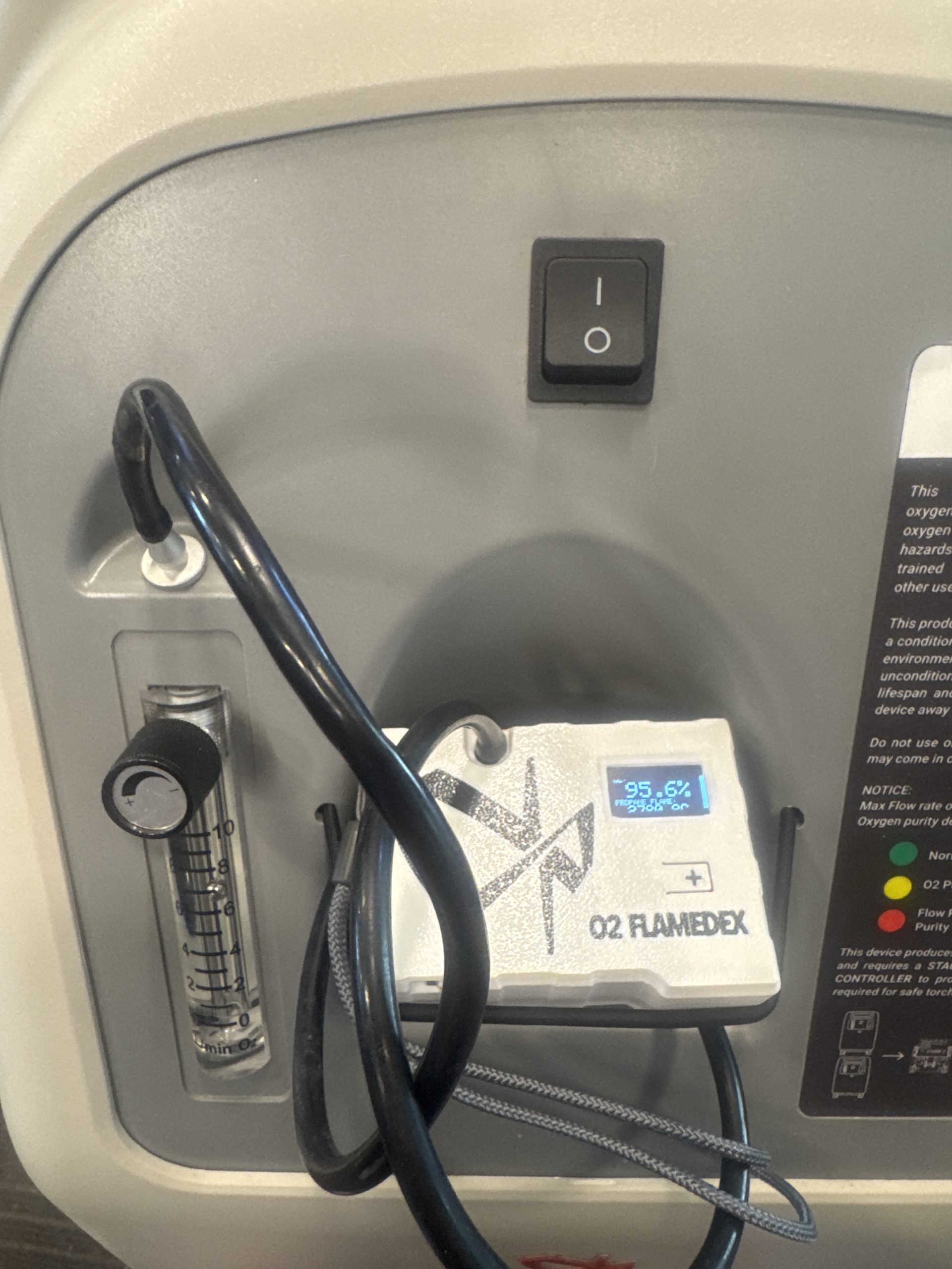
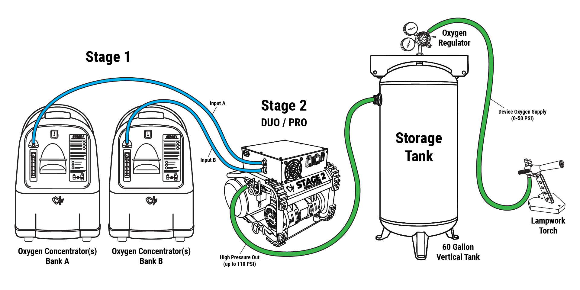
Fixing The Pressure of Oxygen Concentrators for Powering a Flameworking Torch
Oxygen Concentrators can be the life breath of a glass studio, or the source of frustration and a scorched torch face. Read more in our article on upgrading the pressure and flow of O2 Concentrators for optimal lampworking.
Written by

What is The Proper Name of Oxygen and Gas Fittings for Torch Hook Up and Connections
Learn how to read CGA fitting numbers with our clear explanation of the CGA-023 B code. Understand CGA standards, thread direction, size classes, and common fitting types to ensure safe and accurate gas connections.
Written by

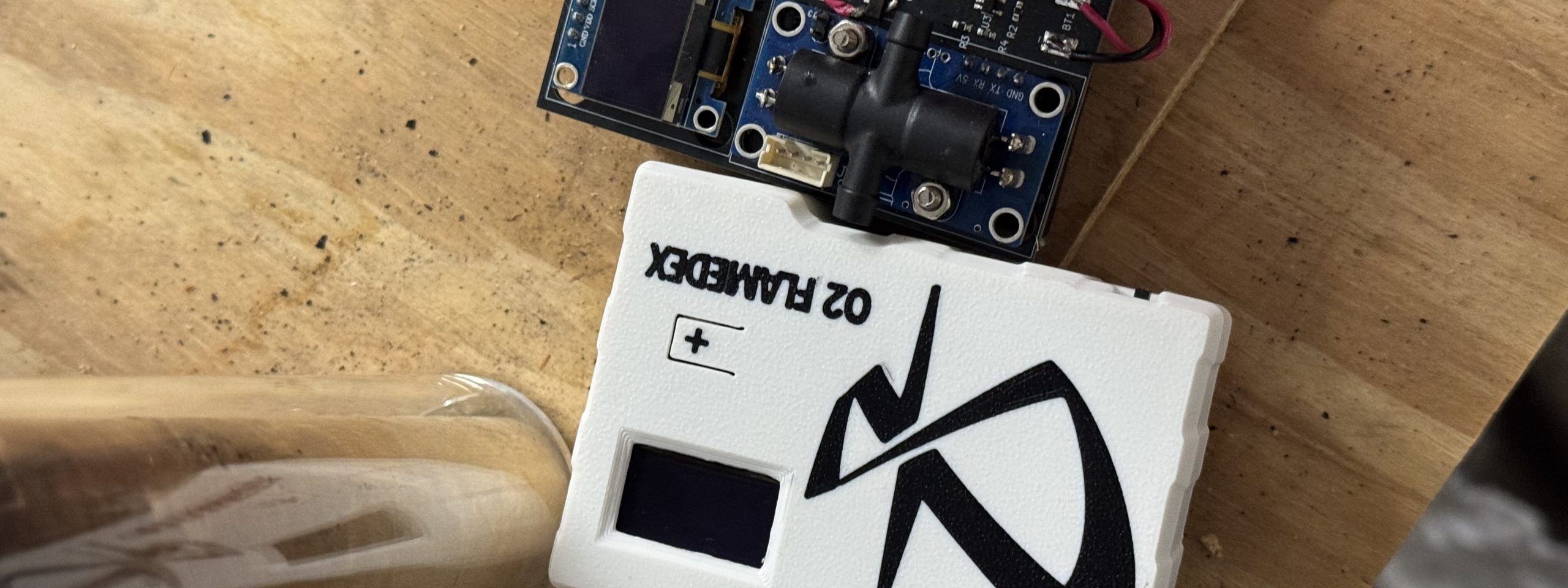
Choosing the Right Oxygen Purity Meter for PSA Systems in Torch Work: Why We Built a Self-Calibrating Ultrasonic Option
If you use a PSA oxygen system for glass, metal, or flame work, you’ve probably wondered how to verify the purity coming off your concentrators and into storage. We’re introducing a lower-cost, self-calibrating oxygen purity meter that uses an ultrasonic module (speed-of-sound) rather than the typical electrochemical, paramagnetic, or zirconia techniques. This post explains the…
Written by

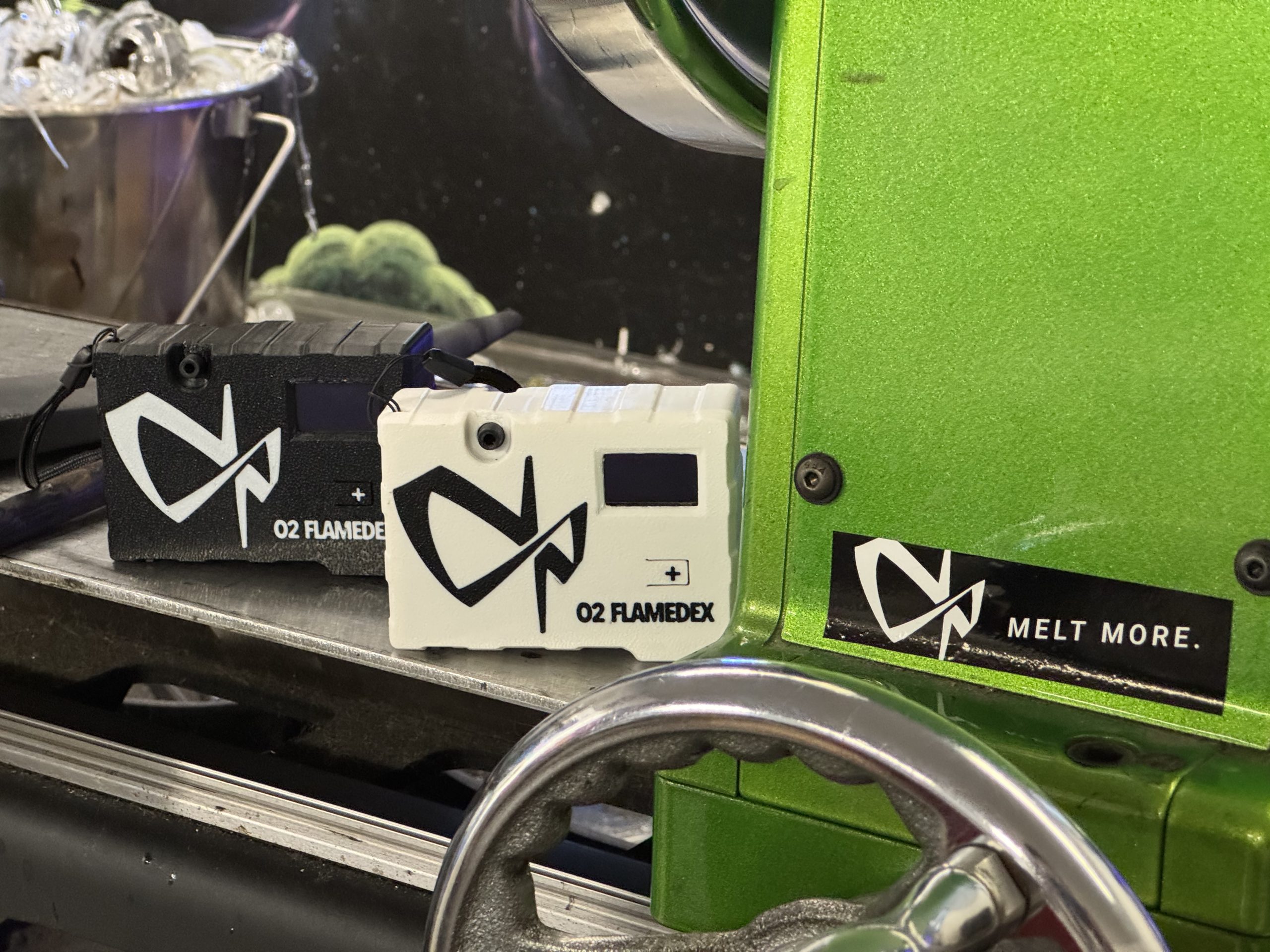
Ultrasonic Technology Makes Oxygen Purity Measurement More Affordable for Torch Workers
Introducing: The O2 Flamedex! View oxygen purity and resulting maximum flame temperatures in Celcius and Farenheit. Runs on 3xAA batteries. When it comes to oxy-fuel cutting and welding, oxygen purity isn’t just a number — it’s the backbone of consistent performance. If oxygen purity dips, flame temperature drops, cut quality suffers, and operations become less…
Written by

How Pure Can Concentrated Oxygen Get? The Real Limit — and Why PSA Works for Glassblowers
Concentrators make enriched oxygen using PSA technology. There’s a natural question: How pure can PSA/Concentrated Oxygen actually get, and does that matter at the bench? For glassblowers, oxygen quality shows up in the flame: heat, stability, and how predictably the torch responds when you push your work. Given this importance, why would studios move away…
Written by

Scaling Challenges and Sustainable Solutions in Stage 2 ETL Certification
As we continue refining our machines and processes, the recent ETL inspection of our Stage 2 unit reminded us of two important truths: scaling up comes with greater complexity, and every challenge is an opportunity to reaffirm our commitment to sustainability. Scaling Up Means Scaling the Risks When production moves from single units to batch…
Written by

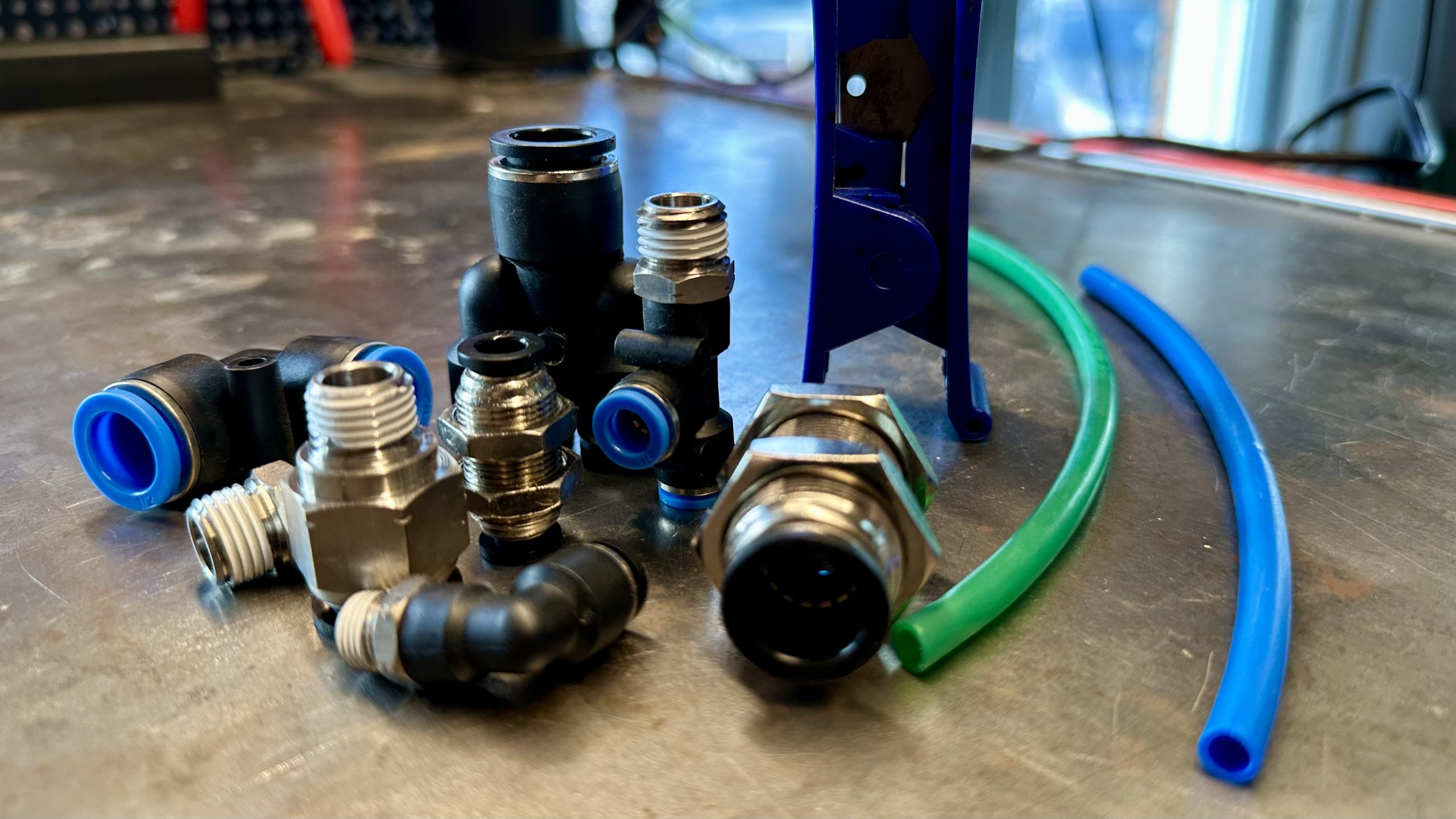
Designing for Durability: Why PTC Fittings and TPU Tubing Outperform Under Pressure
Oxygen compression systems demand reliability. Heat, vibration, and continuous operation can quickly expose the weaknesses of traditional hose clamps or barbed fittings. The result? Leaks, inefficiencies, and safety risks. A better solution is pairing TPU (Thermoplastic Polyurethane) tubing with Push-to-Connect (PTC) fittings. This combination delivers strength, stability, and ease of use. Exactly what oxygen systems…
Written by

Introduction to Oxygen Generation Systems and PSA Technology
In a wide range of industries—from healthcare to manufacturing—oxygen is a critical resource. While bottled or liquefied oxygen has traditionally been supplied through delivery and storage systems, on-site oxygen generation is increasingly becoming the go-to solution for businesses and facilities seeking a more reliable, cost-effective, and scalable oxygen supply. One of the most popular technologies…
Written by