Author: dpgroup
Pressure Relief Valves (PRVs) for Compressed Gas Systems
A pressure relief valve is one of the most important safety parts on an air compressor. Its job is simple. If the pressure inside the system gets too high, the valve opens and lets air escape preventing serious incident. This helps protect the compressor, air tank, hoses, and tools from damage. It also helps keep…
Written by

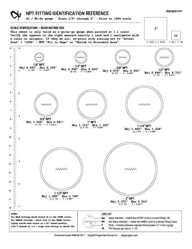
Free Printable NPT Fitting Reference Sheet
Getting your system plumbed up, but you don’t know what to order? The outlet, the inlet, the bushing you pulled out of a drawer — what size are they? Guess wrong and you’re waiting even longer for the right part – taking multiple trips to the store or weeks waiting for orders. Print this one-page…
Written by

Rent-to-Own Oxygen System vs Oxygen Bottle Rental Costs Calculator Tool
Which should you choose as a lampworker? Renting bottles or making oxygen on-site? Oxygen costs vary widely depending on location, supplier, and usage. This comparison is designed to help you determine whether rent-to-own makes sense for your specific situation. Typical Oxygen Rental Costs (What We See in the Field) Cost Component Typical Low End Typical…
Written by
Preparing a Second-Hand Tank for O₂ Storage
We outline the essential steps for preparing a second-hand steel tank for safe oxygen storage, from proper degreasing and rust treatment to thorough drying and inspection. By carefully removing contaminants and moisture, we ensure the tank is clean, compliant, and ready for reliable O₂ service while reducing the risk of combustion and contamination.
Written by

Fixing The Pressure of Oxygen Concentrators for Powering a Flameworking Torch
Oxygen Concentrators can be the life breath of a glass studio, or the source of frustration and a scorched torch face. Read more in our article on upgrading the pressure and flow of O2 Concentrators for optimal lampworking.
Written by

What is The Proper Name of Oxygen and Gas Fittings for Torch Hook Up and Connections
Learn how to read CGA fitting numbers with our clear explanation of the CGA-023 B code. Understand CGA standards, thread direction, size classes, and common fitting types to ensure safe and accurate gas connections.
Written by
Choosing the Right Oxygen Purity Meter for PSA Systems in Torch Work: Why We Built a Self-Calibrating Ultrasonic Option
If you use a PSA oxygen system for glass, metal, or flame work, you’ve probably wondered how to verify the purity coming off your concentrators and into storage. We’re introducing a lower-cost, self-calibrating oxygen purity meter that uses an ultrasonic module (speed-of-sound) rather than the typical electrochemical, paramagnetic, or zirconia techniques. This post explains the…
Written by

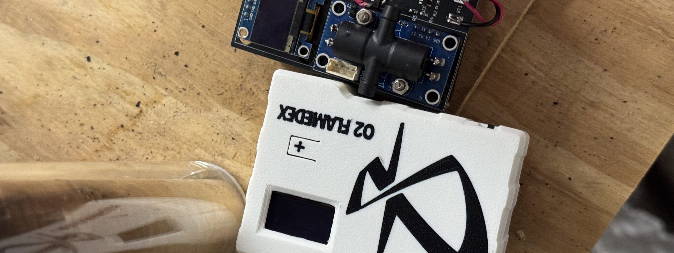
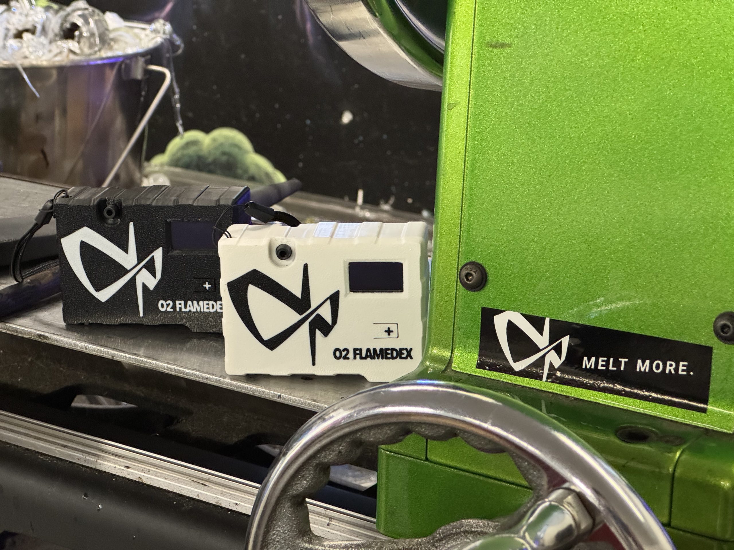
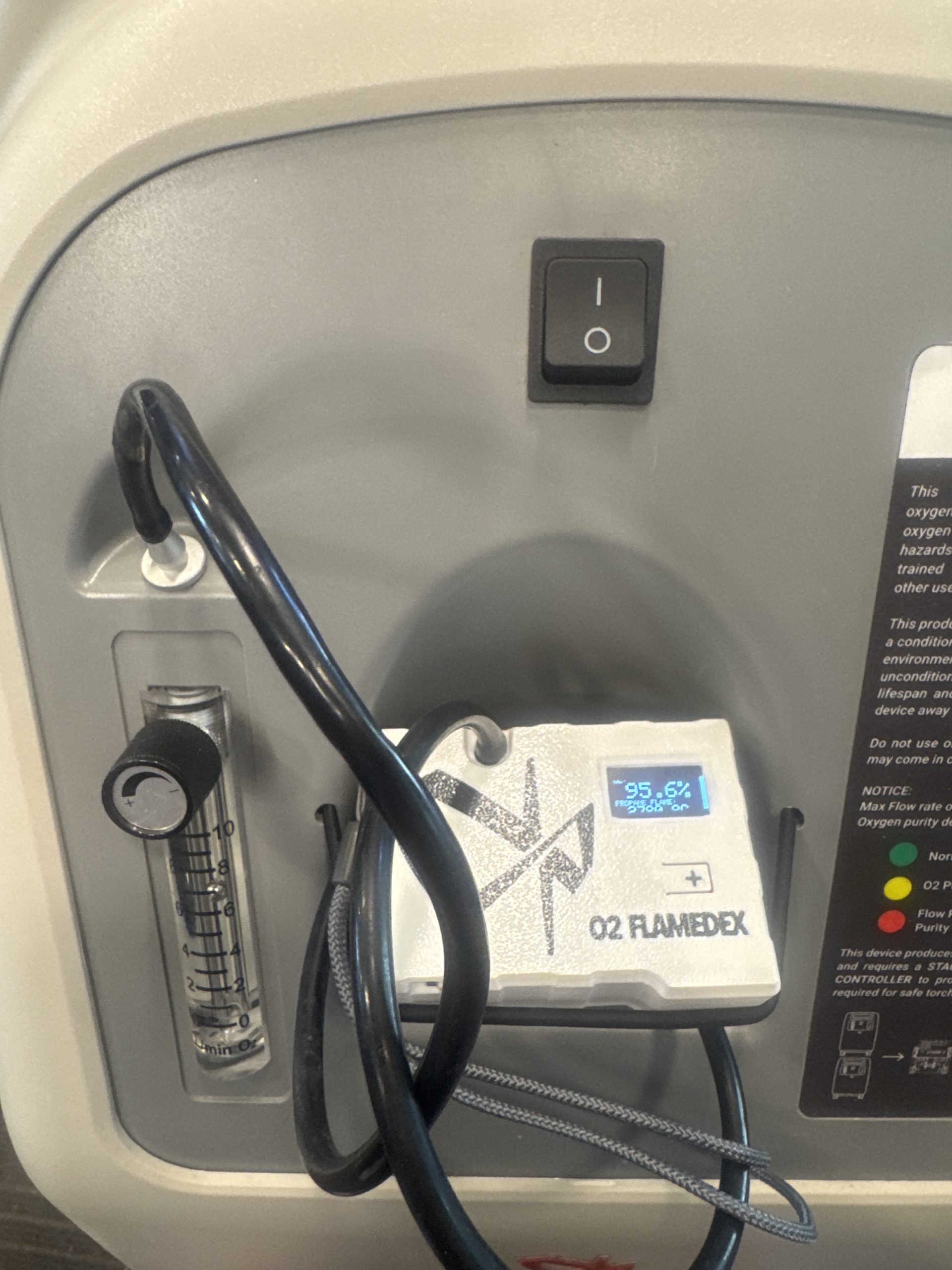
Ultrasonic Technology Makes Oxygen Purity Measurement More Affordable for Torch Workers
Introducing: The O2 Flamedex! View oxygen purity and resulting maximum flame temperatures in Celcius and Farenheit. Runs on 3xAA batteries. When it comes to oxy-fuel cutting and welding, oxygen purity isn’t just a number — it’s the backbone of consistent performance. If oxygen purity dips, flame temperature drops, cut quality suffers, and operations become less…
Written by

How Pure Can Concentrated Oxygen Get? The Real Limit — and Why PSA Works for Glassblowers
Concentrators make enriched oxygen using PSA technology. There’s a natural question: How pure can PSA/Concentrated Oxygen actually get, and does that matter at the bench? For glassblowers, oxygen quality shows up in the flame: heat, stability, and how predictably the torch responds when you push your work. Given this importance, why would studios move away…
Written by

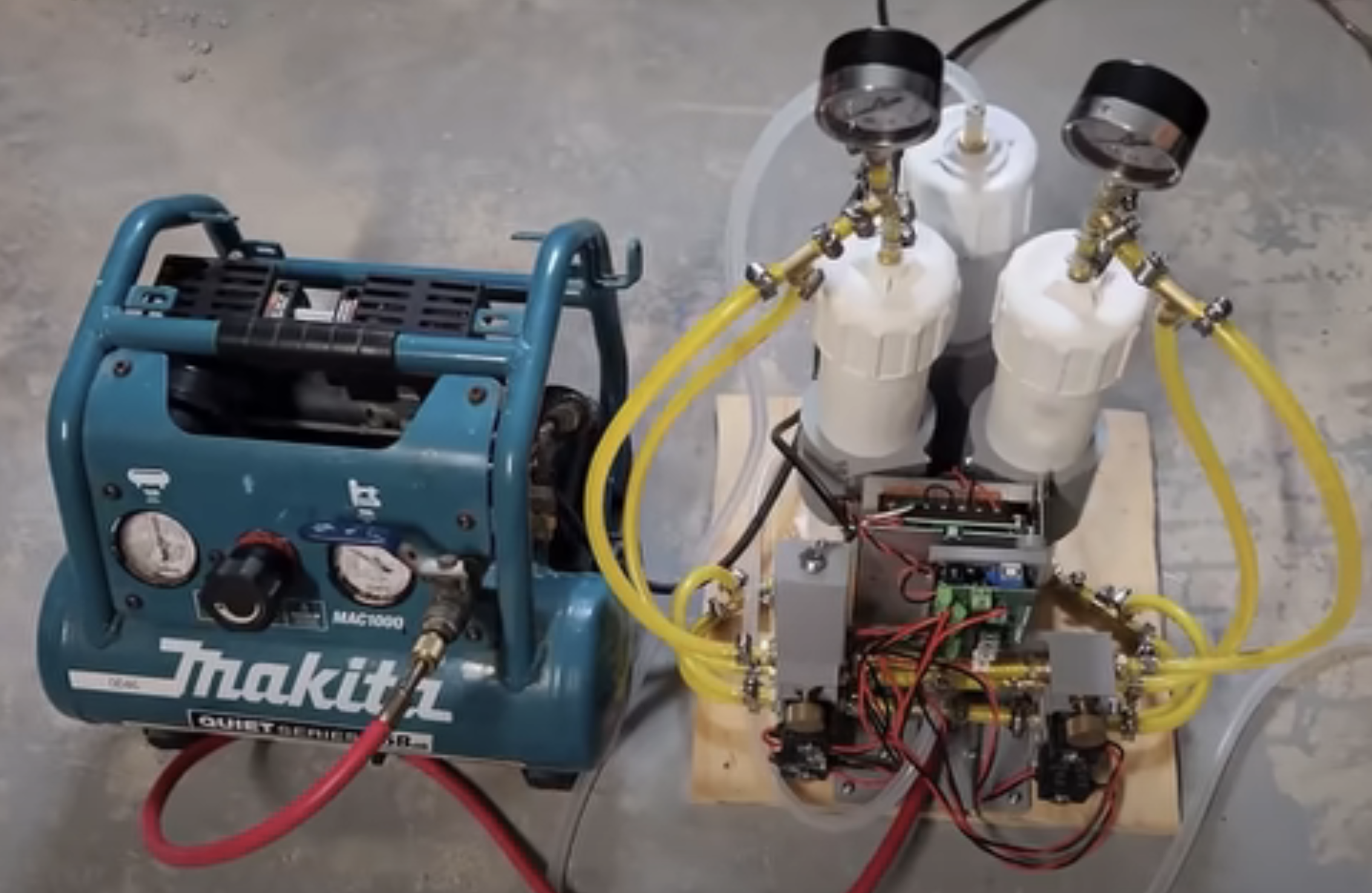
DIY Oxygen Concentrator Projects with Open-Source Designs
Watch How A DIY Oxygen Concentrator is Made If you’ve ever wanted to understand how a PSA-based oxygen concentrator works — or even build one yourself — the above videos offer clear, step-by-step examples. This is more than a DIY tutorial: it’s a working blueprint for builders, technicians, and system designers who want insight into…
Written by